

Components testing services
A COMPLETE SET OF KNOW HOW, METHODS, EQUIPMENTS AND TESTERS FOR:
High power semiconductors characterization
Natural air, forced air and liquid cooled heatsink characterization
Contact surfaces quality evaluation
Power assemblies characterization

| ROUTINE AND TYPE TESTS OF POWER SEMICONDUCTORS | |||
|---|---|---|---|
| DEVICES | TYPE OF TEST | CAPABILITY | TEMPERATURE RANGE |
|
Diodes Press-pack Thyristors press-pack GTO Press -pack Diodes insulated module Thyristors insulated |
Repetitive and non repetitive on-state and reverse |
up to 7 kV; 400 mA; |
-70 °C ÷ +190 °C |
| On state voltage | up to 10 V; 10 kA | +25 °C ÷ +190 °C | |
| Recovery characteristics |
I = 10 ÷ 4000 A; diI/dt = 0.4 ÷ 1000 A/μs; VR = 10 ÷ 100 V; |
+25 °C ÷ +190 °C | |
|
Press-pack Thyristors Insulated Module Thyristors |
Trigger characteristics | -70 °C ÷ +190 °C | |
|
Turn off dv/dt |
I = 10 ÷ 4000 A; di/dt = 0.4 ÷ 300 A/μs; VR = 10 ÷ 100 V; VD = 200 ÷ 3000 V; dv/dt = 20 ÷ 2000 V/μs; |
+25 °C ÷ +140 °C | |
| Press-pack GTOs | Dynamic characteristics | up to IT=3500 A; VD = 4500 V |
+25 °C ÷ +120 °C |
|
Press-pack IGBTs Insulated Module IGBTs |
Static characteristics | up to 7 kV; up to 6 kA |
+25 °C ÷ +150 °C |
|
Press-pack Diodes Press-pack Thyristors Press-pack GTOs Press-pack IGBTs |
Sealing tests | Mass spectrometer, Tracer gas: He |
+25 °C |
|
Press-pack Diodes Press-pack Thyristors Press-pack GTOs Insulated Module Diodes Insulated Module Thyristors |
Surge tests | 1 kA - 70 kA with or without reverse voltage reapplied |
+25 °C ÷ +175 °C |
| Press-pack Devices and Insulated Modules | High temperature blocking life test | up to 6 kV | +80 °C ÷ +150 °C |
| Press-pack Devices | Thermal resistance junction - heatsink tests | ||
| ROUTINE AND TYPE TESTS OF POWER ASSEMBLIES | ||
|---|---|---|
| TYPE OF TEST | EQUIPMENT | CAPABILITY |
| Input regulator for power assemblies testing area | Three phases high power variable voltage supply | 0 ÷ 400 V (120 kVA) |
| No load high voltage test | Three phases high voltage supply | 0 ÷ 3 kV (50 kVA); 0 ÷ 8 kV (3,5 kVA) |
| High current supply for thermal tests on rectifier bridge | Three phases high current supply | continous current up 10 kA (75 kVA) 1 min pulse 16 kA |
| Insulation tests | Electric strength voltage test equipment | up to 25 kV |
| Source of DC voltage equivalent to railway line | DC voltage supply | up to 4 kV - 30 A or 400 V - 300 A |
| Source for DC link supply | Adjustable high voltage power supply | up to 10 kV, 1A |
| Static and dynamic test for power modules and assemblies | Multitester for module and assemblies | Static 6000 V; 1000 A Dynamic 2000 V; 1000 A |
| MECHANICHAL TESTS OF POWER SEMICONDUCTORS AND POWER ASSEMBLIES | ||
|---|---|---|
| TYPE OF TEST | EQUIPMENT | CAPABILITY |
| Dimensional | Micrometer | 0,001 mm |
| Visual inspection | Optic microscope | 1000 x |
| Rugosity | Roughness tester | up to Ra = 0,4 |
| Flatness | Flatness tester | 0,001 mm |
| Thickness of plating layer | Fischerscope X-rays | Different plating layers and substrates |
| RELIABILITY TESTS OF POWER SEMICONDUCTORS | ||
|---|---|---|
| TEST CONDITION | TYPYCAL TEST DURATION | |
| Thermal power cycling tests | Sine wave current 50 Hz ∆ T = 70 – 80 °C I conduction (A) = up to 3000 A Cooled by water flow t cycle (s) = from 1 sec to 10 mins |
Higher than 1000 cycles |
| High temperature blocking life test | Sine wave voltage 50 Hz Tj = Tj max V = 0.8 VDRM (VRRM) |
T = 4 - 168 h |
| High temperature storage test | T (°C) = high value of storage Temperature (up to 200 °C) |
T = 168 h |
| Low temperature store test | T (°C) = low value of storage Temperature (down to -70 °C) |
T = 168 h |
| Passive cycling test | Thi = 150 °C Tlo = -70 °C |
10 cycles |
FAILURE ANALYSIS ON HIGH POWER SEMICONDUCTORS
Poseico may perform a failure analysis on failed devices (press-pack or insulated module devices) in order to evaluate the potential failure causes occurred during the device operation on field. Thanks to its own database, Poseico may provide a quick and deep evaluation of failure conditions and perform specific laboratory tests (mechanical and electrical) to help the Customer to mitigate potential wrong working conditions of the final application.
AUTHENTICITY CHECKS
Counterfeit goods span across multiple industries including the Power Electronics one. Poseico is fighting against this unpolite competition and it offers a complete service in order to analyze if semiconductors, branded Poseico or other, are original or fake.
MOUNTING RECOMMENDATIONS
In order to ensure effective cooling, good current conduction and reliability, in the assembly of Power Semiconductors, it’s important to observe some recommendations with a particular focus on heatsink preparation and clamping system. The recommended procedure is reported below:
USING BAR CLAMPING SYSTEM
- - clean the mounting area (a) of both heatsinks before with “abrasive rubber” and than with alcohol.
- - clean the mounting surfaces of the semiconductor with alcohol.
- - apply a thin film of mounting grease (b) on both mounting surfaces of the heatsinks.
- - put the semiconductor between the two heatsinks and rotate it to spread the contact grease.
CAUTION: each guide pin should be located in the center hole.
- - pre-assemble the clamp housing if necessary
- - place the pre-assembled portion of the clamp through the heatsink and the semiconductor assembly.
- - place over the upper heatsink the second part of the clamp, equipped with its spring system and hardware parts.
- - tighten by “fingers” the screws and put all the assembly in position.
CAUTION: all the surfaces must be parallel before tightening.
- - tighten the screws half a turn until the pressure indicating system shows that the required pressure has been achieved.
USING BOX CLAMPING SYSTEM
- - clean the mounting area (a) of both heatsinks before with “abrasive rubber” and than with alcohol.
- - clean the mounting surfaces of the semiconductor with alcohol.
- - apply a thin firm of mounting grease (b) on the surfaces of the device.
- - put the box clamp over the device ensuring that the pins are correctly located.
- - put the square steel plate over the central rod, putting bolts through the clamp whilst holding it firmly in place.
- - screw the bolts “finger tight” then alternatively, clockwise, half a turn until the box touches the heatsink all the way round.
CAUTION: use a torque wrench to apply the right clamping force.
- (a) recommended tolerances over the device mounting area: flatness 30 micron, roughness 2 micron
- (b) recommended mounting grease: contactal hpg Note: before mounting the assembly, a leakage test must be performed to verify the electrical integrity.
Maximum allowable average current
In this catalogue the average current ratings are mostly specified for temperatures of: Th = 55°C. Tc = 85°C at 180° sine wave. For other temperatures, the current can be calculated using the following formulas applicable up to 400 Hz:
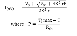
- I(AV) = IT(AV) for thyristors, IF(AV) for diodes
- Vo = VT(TO) for thyristors, VF(TO) for diodes
- T = Tc or Th
- Rth = Rth(j - c) or Rth(j - h)
- r = rT for thyristors, rF for diodes
- K = 1 for direct current
- K = (π /2) for 180° sine wave
- K = √3 for 120° rectangular wave
- K = √2 for 160° rectangular wave